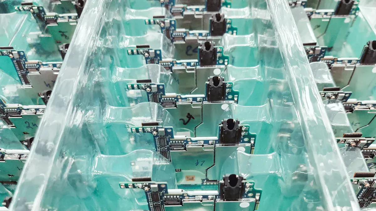
Designing injection mold designs for small electronic components presents unique challenges. Achieving precise dimensions and maintaining uniformity in complex geometries can be daunting. Small errors lead to defects like warping or shrinkage, impacting functionality and durability. Addressing these issues ensures cost-efficiency and quality.
By tackling these challenges, you can enhance precision and streamline production.
Precision in wall thickness plays a critical role in the success of injection mold design. Small electronic components often require micron-level tolerances to function correctly. Even minor deviations can lead to assembly failures or reduced performance. For example:
- Material shrinkage during cooling can cause dimensional inaccuracies.
- Uneven wall thickness can result in warping or stress concentration.
- Advanced quality control ensures each part meets strict specifications.
Simulation tools like SOLIDWORKS Plastics help predict and prevent defects early in the design process. These tools allow you to optimize wall thickness and runner systems, reducing costly rework and improving production efficiency. By maintaining uniform wall thickness, you can enhance the durability and functionality of injection molded parts.
Undercuts and complex features present significant challenges in mold design. These elements often complicate the ejection process and increase production costs. However, several techniques can help you manage these challenges effectively:
- Adjusting the parting line to minimize undercuts.
- Using sliders, lifters, or side actions to release undercut features.
- Implementing bump-offs to create undercuts without additional components.
- Adding hand-loaded inserts for intricate designs.
Design for manufacturability (DFM) feedback is essential when dealing with complex geometries. It helps you identify potential issues early and optimize the mold design for efficiency. By employing these strategies, you can produce high-quality parts while minimizing production delays.
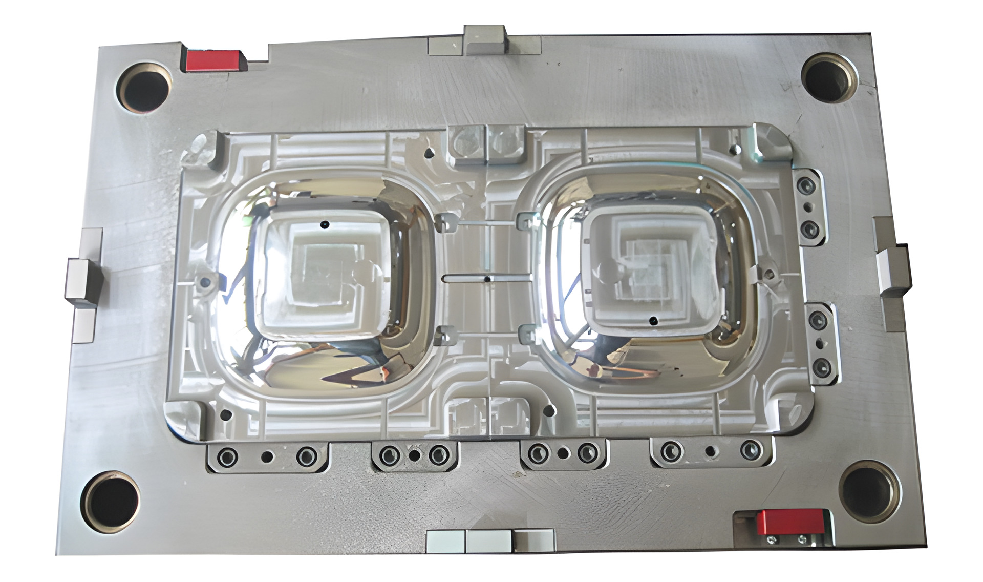
The placement of the parting line significantly impacts the mold's complexity and the quality of the final product. A well-designed parting surface simplifies the mold structure and reduces manufacturing costs. Proper gate placement also enhances the solidification process, leading to fewer defects. For instance:
| Evidence Type | Description | Impact | |---------------------|-----------------------------------------------------|-----------------------------------------------| | Parting Surface | Affects mold design complexity. | Simplifies mold structure, reduces costs. | | Gate Position | Enhances solidification of molded components. | Results in faster solidification, fewer defects. |
Strategic parting line placement ensures that the mold can handle intricate designs without compromising on quality. It also reduces the risk of flash, which can affect the appearance and functionality of the final product.
Warping and shrinkage are common issues in injection mold design. These defects occur when uneven cooling or material properties cause parts to deform or reduce in size. You can prevent these problems by focusing on a few key strategies:
Simulation tools can also help you predict and address potential warping or shrinkage issues before production begins. By analyzing the mold flow and cooling process, these tools allow you to make adjustments early, saving time and resources.
Proper venting and ejection are critical for producing high-quality injection molded parts. Without adequate venting, trapped air and gases can cause defects like burn marks or incomplete fills. Similarly, poor ejection systems can damage parts during removal.
Here’s how you can address these challenges:
The table below highlights the outcomes of different venting techniques:
| Evidence Description | Outcome |
|---|---|
| Standard venting systems have limited capacity, often insufficient for quality parts. | Indicates need for improved venting solutions. |
| Inserting porous sintered materials reduces injection pressure and scrap rates. | Confirms effectiveness of alternative venting methods. |
| Overflow systems can overcome vent limits, allowing for better part quality. | Highlights benefits of advanced venting techniques. |
| Dynamic venting valves allow rapid air and gas escape, improving mold performance. | Supports the need for innovative venting solutions. |
By implementing these methods, you can enhance mold performance and reduce defects.
Choosing the right material for injection mold design can be complex. Each material has unique properties that affect its performance during molding and in the final product. You must consider factors like temperature resistance, impact strength, and flow characteristics.
Key challenges in material selection include:
To overcome these challenges, collaborate with material experts and conduct thorough testing. For example, the notched Izod test evaluates impact resistance, but you should ensure consistent testing methods to obtain reliable results. By understanding material properties and their implications, you can select the best option for your injection molded parts.
Maintaining uniform wall thickness is essential for achieving high-quality injection molded parts. Variations in thickness can lead to uneven cooling, causing defects like warping, residual stress, and differential shrinkage. When you ensure consistent wall thickness, the plastic flows evenly during molding, preventing air traps and unbalanced filling patterns. This approach also minimizes residual stresses, reducing the risk of warpage after ejection.
Simulation tools confirm that thinner walls cool faster, resulting in lower crystallinity and shrinkage, while thicker walls cool slower, increasing both. By keeping the thickness uniform, you can avoid these issues and enhance the overall manufacturability in mind.
Tip: Use simulation software to analyze wall thickness and predict potential defects before production begins. This proactive step saves time and resources.
Abrupt changes in geometry often create stress concentrations in molded parts. These stress points can weaken the part and lead to premature failure. Gradual transitions, such as fillet radii or tapers, help distribute stress more evenly across the part. Smoothing critical areas in the design prevents stress from accumulating in localized regions, improving the part's durability.
For example, incorporating fillets at sharp corners reduces the likelihood of cracks forming under load. This simple adjustment enhances the part's strength without increasing production complexity. Gradual transitions also improve the flow of molten plastic, ensuring a more consistent fill and reducing the risk of defects.
Note: Always evaluate stress flow during the design phase to identify areas where gradual transitions can improve performance.
Overmolding is a powerful technique that combines multiple materials into a single part, enhancing its functionality and aesthetics. This process involves molding one material over another, creating a seamless bond between the two. Overmolding improves grip, comfort, and durability, making it ideal for applications in the medical, automotive, and electronics industries.
| Application Area | Performance Enhancement |
|---|---|
| Medical Industry | Ergonomic grips on surgical tools, protective coatings for better handling and hygiene |
| Automotive Industry | Improved grip, reduced vibration, weather resistance in components |
| Electrical Devices | Protection from moisture and dust, enhancing reliability |
| General Products | Enhanced aesthetics and user-friendliness through material combinations |
Overmolding also creates effective seals, protecting sensitive components from moisture and dust. For example, in electronics, this technique ensures reliability by preventing environmental damage. By combining materials with complementary properties, you can achieve features like improved vibration resistance and enhanced user experience.
Tip: Collaborate with experienced partners during the design phase to maximize the benefits of overmolding. Strategic partnerships streamline processes and reduce costs.
Gate placement plays a crucial role in ensuring the quality and efficiency of injection mold design. The gate serves as the entry point for molten plastic into the mold cavity. Placing it strategically can prevent defects like uneven fills, shrinkage, and warping. You should consider several factors when optimizing gate placement to achieve the best results.
By focusing on these aspects, you can enhance the mold's performance and improve the final product's quality. Simulation tools can also help you visualize material flow and test different gate placements before production begins. This proactive approach saves time and reduces costly errors.
Tip: Always test gate placement during the design phase to identify potential issues early and refine your strategy.
Draft angles are essential for ensuring smooth ejection of parts from the mold. Without proper draft angles, parts may stick to the mold, causing damage or deformation. Incorporating the right angles into your design can significantly improve production efficiency and product quality.
| Statistic | Impact |
|---|---|
| Draft angles of 0.5° to 2° ease product removal, reducing damage risk. | Ensures smooth ejection and minimizes part defects. |
| Optimal angles can decrease defects by up to 30%, improving quality. | Enhances the overall reliability of the final product. |
| Correct angles can enhance production rates by 15-20%. | Speeds up the manufacturing process, saving time and resources. |
| Optimal angles can extend mold life by up to 25%. | Reduces wear and tear, lowering maintenance costs. |
Draft angles also reduce friction during ejection, allowing parts to separate easily from the mold. This minimizes deformation and enhances dimensional accuracy. By incorporating draft angles of 0.5° to 2°, you can achieve a balance between ease of ejection and part quality.
Note: Evaluate the draft angles during the design phase to ensure they align with the material's shrinkage properties and the mold's geometry.
Material selection is a critical aspect of injection mold design. Each material has unique properties that influence its behavior during molding and its performance in the final product. Collaborating with material experts can help you make informed decisions and optimize your design for specific applications.
| Industry | Techniques Used | Outcomes |
|---|---|---|
| Automotive | CAD, High-Performance Materials | 20% reduction in vehicle weight, improved fuel efficiency, lower emissions. |
| Medical Devices | Rapid Prototyping, Quality Assurance Protocols | Successful launch of surgical instruments, compliance with FDA, reduced defects. |
| Consumer Goods | Modular Mold Design, Advanced Injection Molding | 30% increase in sales, adaptability to market trends. |
| Aerospace | Finite Element Analysis, Advanced Composite Materials | 15% reduction in fuel consumption, enhanced safety and reliability in aircraft designs. |
For example, in the automotive industry, using high-performance materials and CAD tools has led to lighter vehicles with better fuel efficiency. In medical devices, rapid prototyping and strict quality assurance protocols have ensured compliance with regulatory standards while reducing defects. These examples highlight the importance of expert collaboration in achieving superior results.
Tip: Work closely with material specialists to test and validate your material choices. This ensures your design meets both functional and aesthetic requirements.
Computer-Aided Design (CAD) software is a cornerstone of modern injection mold design. It allows you to create intricate and precise designs that would be nearly impossible to achieve manually. With CAD, you can visualize every detail of your mold, ensuring accuracy and reducing errors before production begins.
Different CAD systems offer varying levels of precision and user satisfaction. For example, optimized systems score between 9.05 and 9.97 in user satisfaction, outperforming traditional systems, which range from 6.05 to 7.25. Popular tools like CATIA and PTC Creo also rank highly, with scores above 8. This data highlights the importance of choosing the right software to meet your design needs.
Tip: Use CAD software to experiment with different mold designs and identify potential issues early. This proactive approach saves time and resources.
| CAD Software | User Satisfaction Score (Range) |
|---|---|
| Traditional System | 6.05 - 7.25 |
| Autodesk Fusion 360 | 7.15 - 8.43 |
| Unigraphics | 7.07 - 7.97 |
| Ptc Creo | 7.64 - 8.45 |
| CATIA | 8.02 - 8.97 |
| Optimized System | 9.05 - 9.97 |
Simulation tools play a vital role in optimizing mold designs for plastic injection molding. These tools allow you to test your designs virtually, identifying potential issues like short shots, weld lines, or uneven cooling before production begins. By using simulation software, you can save time and reduce costly errors.
For example, fine mesh simulations provide highly accurate results, closely matching actual molded parts. They reveal issues like hesitation and short shots while producing smoother weld lines. In contrast, coarse mesh simulations are less accurate, showing jagged weld lines and missing some defects. This demonstrates the value of using advanced simulation tools to refine your designs.
| Mesh Density | Observations on Results | Accuracy Compared to Actual Parts |
|---|---|---|
| Coarse Mesh | Hesitation noted, no short shots; jagged weld lines | Less accurate, shows full-width weld line |
| Fine Mesh | Shows hesitation and short shots; smoother weld lines | More accurate, correlates closely with actual molded parts |
Note: Always use fine mesh settings in your simulations for the most reliable results.
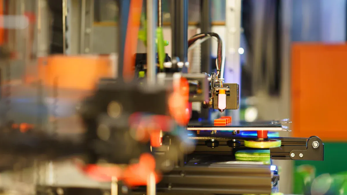
3D printing has revolutionized prototyping in injection mold design. It allows you to create prototypes quickly and cost-effectively, enabling faster iterations and reducing development time. For instance, a defense firm used 3D printing to produce 60 parts for a UAV system demonstration in just 10 business days, a significant improvement over traditional methods.
This technology is also gaining popularity for low-volume production. In 2023, 21% of survey respondents reported using 3D printing for end-use parts, up from 20% in 2022. The trend shows a shift toward using 3D printing for small production runs, where it can be more economical than traditional injection molding.
Tip: Use 3D printing to test your designs before committing to full-scale production. This approach minimizes risks and ensures better results.
Automation and artificial intelligence (AI) have transformed injection mold design. These technologies streamline processes, reduce errors, and improve efficiency. By automating repetitive tasks, you can focus on more complex design challenges. AI tools analyze vast amounts of data, offering insights that enhance decision-making.
For example, AI-powered software predicts potential defects in mold designs. It evaluates factors like material flow, cooling rates, and stress points. This allows you to make adjustments before production begins. Automation also improves consistency. Robots handle tasks like material loading and part ejection with precision, reducing human error.
You can also use machine learning algorithms to optimize production schedules. These systems analyze historical data to predict maintenance needs, minimizing downtime. Additionally, AI-driven quality control systems inspect parts in real-time, identifying defects immediately. This ensures that only high-quality components move forward in the production process.
Tip: Start small by automating one aspect of your workflow. Gradually expand as you see the benefits.
Advanced inspection tools ensure the quality of injection molded parts. These tools combine software and hardware to deliver precise measurements and faster results. By using these technologies, you can detect defects early and maintain high standards.
Dimensional inspection tools compare parts to their CAD models. This process identifies deviations and ensures accuracy. Recent advancements have reduced inspection time by 70%, allowing you to complete quality checks faster. This saves time and improves overall efficiency.
Non-contact inspection methods, like laser scanning and CT scanning, provide detailed 3D images of parts. These methods capture intricate details without damaging the components. You can use these tools to verify complex geometries and ensure compliance with design specifications.
Note: Regularly calibrate your inspection tools to maintain their accuracy and reliability.
Warping in micro-connector molds often results from uneven cooling or material shrinkage. These issues can compromise the dimensional accuracy of the final product. You can address this challenge by ensuring uniform cooling and selecting materials with low shrinkage rates. For instance, dimensional inconsistencies, including warping and shrinkage, account for up to 30% of HDPE molding issues across various industries.
Simulation tools play a vital role in identifying potential warping risks during the design phase. By analyzing the cooling process, you can make adjustments to the mold design, such as adding cooling channels or optimizing wall thickness. These proactive measures reduce the likelihood of defects and improve overall production quality.
Tip: Always test your mold design under simulated conditions to predict and mitigate warping issues effectively.
Proper gate placement is essential for ensuring uniform material flow in sensor housing molds. When you position gates strategically, you can prevent defects like short shots, air entrapment, and non-uniform part quality. Advanced gate placement strategies ensure even material distribution, which enhances the homogeneity of the final product.
Effective gate placement in multi-cavity molds also allows for early adjustments, avoiding costly redesigns. This approach not only improves production efficiency but also reduces material waste. Properly positioned gates are crucial for achieving consistent mold filling, which directly impacts the quality of sensor housings.
Note: Use simulation tools to test different gate locations and identify the optimal placement for your mold design.
Shrinkage in miniature components can lead to dimensional inaccuracies and assembly issues. To prevent this, you should focus on material selection and mold design. Materials with lower shrinkage rates, such as amorphous plastics, are ideal for producing small, precise parts.
Low-waste molding techniques also help minimize shrinkage. For example, Essentra Components achieved a 50/50 ratio of recycled content to virgin plastics in their LDPE product range, using 98% recycled plastic. This approach not only reduces material waste but also enhances the sustainability of the production process.
Tip: Collaborate with material experts to select the best materials for your miniature components, ensuring both precision and sustainability.
Injection mold design for small electronic components comes with unique challenges, from managing complex geometries to preventing defects like warping and shrinkage. By applying solutions such as optimizing gate placement, ensuring uniform wall thickness, and leveraging advanced tools like CAD software and simulation technologies, you can overcome these obstacles effectively. Using best practices and collaborating with experts ensures precision and efficiency in your projects.
Take these strategies into your next design process to achieve high-quality results while saving time and resources.
Warping usually happens due to uneven cooling or inconsistent wall thickness. When parts cool at different rates, they shrink unevenly, causing deformation. You can prevent this by ensuring uniform cooling and maintaining consistent wall thickness throughout the design.
You should consider factors like temperature resistance, shrinkage rate, and flow characteristics. Collaborate with material experts to test options and ensure the material meets your product's functional and aesthetic requirements.
Gate placement affects material flow and cooling. Poor placement can lead to defects like air traps or uneven fills. Strategic positioning ensures uniform material distribution, reducing defects and improving the quality of the final product.
Tools like CAD software, simulation programs, and 3D printing streamline the design process. CAD ensures precision, simulations predict defects, and 3D printing allows quick prototyping. These tools save time and improve efficiency.
Draft angles reduce friction between the part and the mold during ejection. This prevents damage and ensures smooth removal. Proper angles also enhance production speed and extend the mold's lifespan.
Tip: Always evaluate draft angles during the design phase to align with material properties.

RM1223, 12F, No.1, Fuji Bldg, No. 6018 Longgang RD. , Longgang Dist., Shenzhen,China.


Tel: 0086-755-89618186

Contact: Paul Hu 0086-18675501028


 LEAVE MESSAGE